Wednesday, June 17, 2009

Solar powered fireflies

I've been wanting to make something solar powered for some time & figured the firefly kit would be perfect to upgrade to solar power.

I just came across some cheap, second hand, solar powered light fixtures from allelectronics, which is a great place to pick up bits and bats for your electronic projects. Here's the actual solar lights I bought - solar-cell w/charging circuit. As the description says, they come with two solar panels, an LDR, a charging circuit (including - old - batteries) and some LEDs (one LED with this particular one and three with a different product).


As you can see from the pictures, all the components are easily acessible; these seemed perfect for hacking.

My first attempt was pretty simple, I just de-soldered the battery wires from my old JarOFireflies project, snipped the leads to the LED on the solar light kit and soldered the two kits together (the leads to the LED actually have a + and - designation printed on the board).


The LED wires are solid core and quite thick so there's no worry about them snapping under the strain and it made positioning the firefly board easier too. Speaking of which, I cut down the board to a more reasonable size for this project.

I didn't know if the batteries on the solar kit were duff so I left the hybrid out in the sunshine for a full day to charge then brought it indoors to see if it works:


And it does! What a pleasant surprise for something to work first time!

I think I'll cut a hole in the original jar's lid and place the kit in it more securely. Might be nice just to put it out in the garden to confuse the next door neighbours cats who seem to prefer our back yard to their own...

Saturday, June 6, 2009

555 noisemaker

When I started off on the electronics journey I bought the solar powered theramin kit (heliophone) from the makershed I thought it'd be a fun thing for the kids and would be a good starting point for learning to solder. The heliophone uses a solar panel to generate power and produces a clicking noise (the frequency of clicks varies with the intensity of ambient light).

The noisemaker I wanted to make sounds pretty similar but runs off a battery and uses a 555 timer to generate pulses which drive the speaker. Like with the heliophone kit, we alter the frequency of the 'clicks' with changes in ambient light intensity. In this case, it uses the standard "astable" set-up for the 555 and switches R1 for an LDR.

This is a pretty simple set-up and it makes a horrendously annoying noise; so it's perfect for the kids :) My inspiration for this came from this hack-a-day post on tiny-optical-theramins.

I'd already bought a few 555s and LDRs (again due to my eBay issues) so it seemed daft not to make something out of them, especially if the kids were likely to enjoy it.


Here's the final kit. I still want to house it in an interesting way, but I'll have to employ my lady's creative talent to produce something attractive. Maybe I'll paint an alien face on the tin with the LDR sticking through as it's mouth and get the kids to 'feed' it light.


Here's a little test run I did with Ffion, she got distracted pretty quickly by stuff going on in the next room...

Monday, May 18, 2009

ATtiny header board


I've been programming my AVRs using the SparkFun set-up since I started. This is fine for the odd bit of tinkering, but it's a pain having all those wires poked into the programming cable and getting in the way on the breadboard. With an 8-pin dip, there's not a lot of room around the chip for my fat fingers to add wires.


I'd seen these breadboard headers over at Tinkerlog.com and fancied having a go at making my own using the components I'd got lying around (well, ok, I bough the male/female header pins from eBay).

First a rough idea of how I thought it should look:

Then I tried to figure out where the wires should go based on my original set-up (pic of wire mess above) and the ATtiny13 datashet.

Finally I gave a little thought as to where the physical wires were going to go on the perfboard. I decided to swap the position of the 6-pin programming header to make the wiring a little easier. I'm sure there's a better solution, but I was impatient and wanted to get on with it.


Then it was a matter of soldering everything together. I am not an accomplished solderer - this is only my 3rd real soldering project and I'm sure most people wouldn't even consider the ones I've done so far 'projects'.

First off I soldered the headers, push switch (cannibalized from a broken kids toy) and IC socket. This is pretty much how the finished project looks from the top.

Then I realise that I could bridge pins 1 and 8 using the 10K resisitor and have the resistor out of the way of the rest of the wires by having it on the front of the board.

After that it all got a little messy... I need to give myself more time to figure out wiring/routing! I guess this is all a learning experience :)


I kept the insulation on the long wires to prevent short circuits, unfortunately I also ended up melting a lot of the plastic which caused a few issues around pin 5 of the IC socket hence the blackened mess and excess solder around there... I think I managed to sort out my technique a bit better after than and the remaining solder bridges are ok (tips on creating these gratefully received!).

Here it is in action (note that I have to bring in power from the breadboard with my particular programmer).

Saturday, May 9, 2009

Basic AVR IO

I found this very confusing when I started to program my ATtiny13. I read a bunch of different sites/blogs/datasheets to get a feel for it (and am still slightly confused tbh). So, I thought I'd give a brief overview of the basics in a way that makes sense to me. I'm not going to cover input here, just output; but it's a good start.

Here's the key concepts:
  1. AVR uCs are 8-bit devices.
  2. Every AVR has at least some pins which can act as either Input or Output (I/O) devices.
  3. The voltage on the pins can be sensed or controlled via software.
  4. Because of 1. physical pins are logically grouped in sets of 8 as I/O ports. For my ATtiny13 there is only one port (port B) as there are only 8 pins.
  5. Each I/O port has 3 registers associated with it: DDRx, PINx and PORTx (more on this later), where x represents the port (in my case there's only BBRB, PINB and PORTB available).
  6. I/O pins exists as registers inside the processor. It's the software controlled contents of these registers that controls the state and operation of the I/O ports and pins.
  7. The registers are 8-bits in size. Each bit in the register determines the operation of the corresponding number pin (0-7).
DDRx
This register the direction (input/output) of the pins on port x. Again, for the ATtiny13 there is only a port B so we only have DDRB available but on other AVRs there can be many ports (e.g. the atmega168 has 3 ports B, C and D controlling 23 programmable I/O pins) .

A '0' bit makes that port pin act as input.
A '1' bit makes that port pin act as output.

PORTx
This register contains the output state of the pins on port x.

A '0' bit is considered LOW (~0V)
A '1' bit is considered HIGH (~Vcc)

PINx
This register contains the input state of the pins on port x.

A '0' bit indicates that the port pin is LOW (~0V).
A '1' bit indicates that the port pin is HIGH (~Vcc).

So let's take a quick look at the simple code I posted in "Starting with the AVR uC":

1:  #include 
2: #include
3:
4: //LED is wired into pin 7 (PB2)
5: #define LED PB2
6:
7: int main(void){
8: //set data direction register for pin 7 to output
9: DDRB |= _BV(DDB2);
10:
11: //infinite loop
12: while (1) {
13: //turn on the LED
14: PORTB |= _BV(LED);
15: //wait for 1/4 of a second
16: _delay_ms(250);
17: //turn off the LED
18: PORTB &= ~_BV(LED);
19: //wait for 1/4 second
20: _delay_ms(250);
21: }
22: }
5: define LED as PB2. This is just a convenience to allow us to refer to pin 7 as the variable LED. I have the LED wired into pin 7 and this pin is called PB2 according to my datasheet (this can be different for different uCs). PB2 is actually another variable which has been defined thanks to the avr/io.h import statement. I could have used the number 7 instead but I decided to use the name of the pin from the datasheet.

9: This sets bit 7 of DDRB to '1' without affecting any of the other bits in the register. This is the data direction register (DDR), setting a pin in this register to a '1' makes that pin act as an output. I think I should have used the LED variable (defined earlier) rather than DDR2, just for clarity. Ok, next time.

14: Here we manipulate the bits in the PORTB register. This statement sets bit 7 to '1' without affecting any of the other bits in the register. Assigning a '1' to bit 7 of PORTB sets pin 7 to HIGH (~Vcc). This allows current to flow through our LED, lighting it up (or burning it out if you've not added a resistor in serial with it).

18: This statement sets bit 7 of the PORTB register to '0' without affecting any of the other bits. Pin 7 is now LOW, no current flows through the LED (so we've turned it off).

Now, here's a little nugget of info that didn't click until my trip to Noisebridge and a chat with Mitch Altman: I/O pins, by their very nature, are ambivalent towards the direction of current flow. Let me say that again as it's something I didn't realise to begin with and it has an impact on programming LEDs with the AVR. I/O pins don't care which way current flows through them. So, if you have an LED attached to an I/O port (via a resistor) then it can be orientated in either direction (i.e. connected to ground or Vcc, it doesn't matter), the only difference will be whether or not a '1' or a '0' on the corresponding PORTB pin switches it on or off. If the LED is connected to ground, then a '1' in the PORTB register will turn it on; on the other hand, if it's connected to Vcc, then a '0' will switch the LED on.

I know I laboured that last point, but it was non-obvious to me (as a beginner) so I wanted to share. It also meant that those common cathode RGB LEDs I bought aren't as useless as I thought - I was under the wrong impression that I'd only be able to program them using 3 transistors attached to the AVR as switches, because I thought you could only turn on LEDs [with an AVR] by placing a '1' in the PORTB register... doh!

Saturday, May 2, 2009

Jar o' Fireflies

I've seen a few good examples of micro controller controlled fireflies "in a jar" and I wanted to try this for myself. This is by no means a new idea (just take a look at this youtube search and you'll see tons of examples) but I like the idea and I'd already got the basic set-up (see my previous post on AVR programming). All I needed to do was work out the programming (the wiring seems pretty obvious - wire LEDs to uC, wire uC to battery).

What I wanted to do was use all the ATtiny13's 6 output pins to control 6 "fireflies". I'd be happy with just randomly pulsing green LEDs, but I thought it was important to have the LEDs pulse on and off rather than just switch on an off. Here's a youtube video showing fireflies in New York as an example of how the real thing looks. I have a very fond memory of sitting out on a boulder with my brother in Nepal and looking out at a hillside with thousands of fireflies blinking away; we stayed there for ages captivated by the hypnotic display.

So, the standard way to create pulses with an AVR seems to be with pulse width modulation (PWM). Unfortunately mine only has 2 PWM outputs and I wanted to use the parts on hand. A quick search brought up a few possible solutions, but this post on Kevin Mehall's blog was the winner for me. I ended up implementing a software PWM solution based on the code Kevin made public - thanks, Kevin! I've not quite worked out the best way to post code on blogger, when I do I'll post the actual code.

Here's an overview of the parts that went into the project:


The jar was found in the local Savers, the perf board was bought on eBay as were the IC socket, uC, green LEDs and battery pack (all in batches of 10 or more). The wire on the bottom left was scavenged from a broken kids princess wand. The hair clip was an interloper.

My lovely missus decided to improve my project by drawing a few fireflies on shrinkydinks so that I could glue them onto the LEDs after the project was finished:


Here's some photo pr0n of the project in various stages of completion:


And here's something we bought to scare the fireflies:


We got these from Lowes; I think the kids enjoy the venus fly traps much more than the fireflies... c'est la vie.

And, finally, a little video. The flicker isn't actually as bad in real life as it appears in the video, hopefully I'll find a way to remove it completely.

Sunday, April 26, 2009

Starting with the AVR microcontroller

I thought it'd be fun to do some microcontroller (uC) programming.  I've been following the Make blog (and a few others) for a while & love the idea of interactive electronics or even something just a little more complicated than vibrating yogurt pots and wired up LEDs.  I can program already, so it seemed like the logical next step.

Well, firstly I spent a fair bit of time being confused by the huge amount of choice (Arduino, BASIC stamp, PIC, AVR etc.).  The Arduino platform is featured heavily in the Maker community, but it seems a bit heavyweight for what I've been thinking about and besides, if you want to make a few "objects of interest" each one would require their own Arduino board which, at $35 a pop and multiple kids on the rampage, could get very expensive.  PIC and BASIC stamp are both good choices but I decided on the AVR series of uCs for a number of reasons:
  1. They're cheap ($1.50 upwards) and readily available.
  2. You can program them in C (one of the languages I understand).
  3. The compiler and programmer software is available free (I'm using WinAVR, the GNU toolchain is available from the Atmel website).
  4. There's a large and active community of users (e.g. AVRFreaks).
  5. There's an Eclipse plug-in for AVR programming (Eclipse is my favourite IDE).
Unfortunately, in my rush to dive in, I didn't do quite enough reading and ended up buying a batch of 10 ATtiny13s (from eBay). These are great because they have 8 pins (small size), but the problem I found was that they only have two PWM (pulse width modulation) outputs - more on that in a later post though.

So, on top of the software and the chip themselves you also need a way to program the chips.  There are dedicated boards available for this, but I chose to use a USB ISP (In-System Programmer).  With these you can have the chip already placed on a breadboard with the project all wired up, program the chip and see what the effects are immediately.  With the dedicated board, you'd have to program the chip, take it out and place it in the project before you could see the effects.  I made another mistake when buying the USB ISP; in my love of eBay I ended up buying an STK500 copy rather than something genuine from DigiKey (e.g. AVAVRISP2); my knock-off has some compatibility issues with the Eclipse AVR plug in which has meant that I now program and build in Eclipse but use AVR Studio to send the program to the chips.  Ah well, you live and learn.

Anyway, onto the obligatory "hello world" for micro-controllers; the blinking LED!

Firstly, rather than re-iterate what others have said very well, just do what I did and follow the first couple of sessions of the sparkfun tutorials.  I love how ghetto it looks having the wires poked into the programming cable and then into the breadboard; I love it so much that I still have it set-up this way.  The only differences are where to attach the leads to the chip, you can work it out by looking at the ATtiny13 datasheet and comparing the pin layout with that of the ATmega8 used by sparkfun.

The picture below shows what I ended up with.  I'd already added the power supply suggestion from the first lesson, which is the purpose of all the electronics at the head of the breadboard, but I'm using a 9v battery rather than an ac adapter.


Here's the code to make the single LED blink:


#include <avr/io.h>
#include <avr/delay.h>

//LED is wired into pin 7 (PB2)
#define LED PB2

int main(void){
//set data direction register for pin 7 to output
DDRB |= _BV(DDB2);

//infinite loop
while (1) {
//turn on the LED
PORTB |= _BV(LED);
//wait for 1/4 of a second
_delay_ms(250);
//turn off the LED
PORTB &= ~_BV(LED);
//wait for 1/4 second
_delay_ms(250);
}
}

Compile (Project->Build in Eclipse), upload to chip (using AVR Studio) and voila! A blinking LED... not particularly amazing, but it's a good start.

Update: Whilst writing this post I figured out how to get Eclipse to program the uC as well!  AVR Studio can autodetect your programmer, apparently I have an AVR ISP V2.  AVR Studio will also tell you what port it's connected on (is there a way to get the Eclipse plugin to autodetect this?).  In Eclipse I had to open up Project->Properties->AVR->AVRDude->Programmer and edit the configuration.  I set the programmer to "Atmel AVR ISP V2" and overrode the default port (first dialogue box below the programmer list) to com3 - which is the one reported by AVR Studio for my set-up.

Drawing Vibrobots

This was one of my first excursions into building a useful or interesting electronic thing for the kids to play with. The idea is really simple, use the vibrations from a motor to shake a yogurt pot with pens on it. The result should be some interesting patterns drawn on paper (and probably the floor).

I sourced the motors from some dollar store fans and a Nintendo rumble pack (found for $1.50 in a thrift store). The fan motors were great as the were already wired up to a switch and all I had to do was solder on a battery pack. I glued the battery pack on the insides of the pots and poked some holes in the top to attach the wires to the motors. I then weighted one of the fan blades with glue to set up a weight offset and increase the amplitude of vibration.

We made a mistake with the first plastic pot in that we glued on the pen legs to the pot, which meant that they weren't easily changeable (not for kids anyway). I say "we" because the gluing was done by my wife, who is far more adept with a glue gun that I am. 'er indoors also had the idea of putting in some motion activated flashing lights scavenged from various kiddie toys and gluing them onto the inside of the pots. That was a nice touch; thanks love!


For the second pot we glued on the pen lids instead:


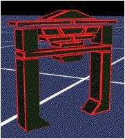
For some reason this larger one reminds me of those ships in Tron...


It turns out that the results from the drawing actually makes for some good wrapping paper! Bonus!


And, finally, a little video: