Monday, May 17, 2010

Pixie-Dust Bottles


It occurred to me whilst making some RGB nightlights for the kids that it'd be fun if they could make the lights change to whatever colour they wanted; kinda like the Philips LivingColors lamp, but about $100 cheaper. Lin suggested that having a few of these (say 5 - 7) would give the kids more room for imaginative fun, so I set about making a prototype and then a few more when that was up and working.

The kids love them (which is always good) and have been claiming that the bottles contain pixie dust (hence the title of this post).

Can you guess what Ffion's favourite colour is? She claims that this is the 'right colour' for pixie dust.


The hardware is pretty straight forward. I used a potentiometer with an in-built on/off switch, like this one, to simplify things. I thought it'd look much nicer than having a separate switch. The rest of the parts are the same as for the RGB nightlights project. The trickiest part was the coding, mainly because I'm doing it late at night when my brain isn't working quite so well...

Ingredients:


1. Potentiometer with switch
2. ATtiny45
3. 8-pin IC socket
4. coin cell battery holder
5. RGB LED (common anode) - I bought mine from EMSL. These are 10mm diffused RGB LEDs.
6. hookup wire, solder etc.

Methods:

I soldered the coin cell holder onto the potentiometer first.

Then I hooked up the RGB LED to the DIP socket. I'm using common anode LEDs so the long LED lead is soldered onto pin 8 of the IC socket. I have the RGB channels/leads connected to pins 5, 6 and 7 and the potentiometer output (middle pin from the pot) connected to pin 3.


After that, all you have to do is solder on the potentiometer's middle terminal to the IC socket and finish off connecting the ground and power connections.


And there we have it. Some kind of strange Borg eye ready to be put somewhere.

We had some plastic kids drink bottles sitting in the recycling bin - they're made from white plastic so I thought they'd diffuse the light nicely. I drilled a hole in the bottle cap for the potentiometer shaft and fitted it all together. Finally, I added a knob (radioshack purchase) to make it a bit prettier and easier to use.


Coding:

I'd already worked out how to do the software PWM (pulse width modulation) and how to measure a variable voltage input using ADC (analogue to digital conversion) so all that needed to be figured out, for this project, was how to map the ADC input values to the desired range of colours.

I wanted to let the kids cycle through the entire spectrum in much the same way the previous night-lights cycled automatically.

So, in the RGB nightlights project there were 6 transitions/steps:
stepRed channel valueGreen channel valueBlue channel valuechanging channelcolour range
125500increase GreenRed to Yellow
22552550decrease RedYellow to Green
302550increase BlueGreen to Cyan
40255255decrease GreenCyan to Blue
500255increase RedBlue to Purple
62550255decrease BluePurple to Red


If we use a 10-bit ADC we have 1024 values (2^10) available for mapping to colours in the above steps. This means that each step can contain 170 values/colours (1024/6 = 170.666...).

So, to map the ADC value to a colour we first assign it to one of the 6 steps and then use it to determine the value of the varying channel (Red/Green/Blue) for that step.

There are 6 steps and each step can have 170 ADC values associated with it. So I binned the ADC values into steps like so:
stepADC value
1< 170
2< 342
3< 512
4< 683
5< 854
6>= 854


Here's an example to clarify: Say the potentiometer is set just over half way, then the ADC value should be between 512 and 683; this would put us in step 4 where the red channel is off, the blue channel is completely on (255) and the green channel is varying (in this step the green levels are decreasing from 255 -> 0 as the ADC value increases from 512 -> 683). We calculate the green level by translating the ADC range to 0 - 170 (in this case by subtracting 512) and then multiplying by a scaling factor (255/170) to transform the 0 -> 170 range to a 0 -> 255 range. If we're increasing the level of the channel (steps 1, 3 and 5) then we just use this scaled value as the channel value. If we're decreasing the level of the channel (as is the case for step 4) then we inverse the scaled value by subtracting it from 255.

Here's the bit of code that sets the RGB values (see the complete listing here: selectableColourLight.c):

#define SCALING_RANGE 170
#define SCALING_FACTOR 255/SCALING_RANGE

...

void setRgbLevels(uint16_t pValue)
{
 if(pValue < SCALING_RANGE)
 {
  mRgbValues[RED_INDEX]   = 255;
  mRgbValues[GREEN_INDEX] = pValue * SCALING_FACTOR;
  mRgbValues[BLUE_INDEX]  = 0;

 }
 else if(pValue < 342) //SCALING_RANGE * 2
 {
  mRgbValues[RED_INDEX]   = 255 - ((pValue - SCALING_RANGE) * SCALING_FACTOR);
  mRgbValues[GREEN_INDEX] = 255;
  mRgbValues[BLUE_INDEX]  = 0;
 }
 else if(pValue < 512) //SCALING_RANGE * 3
 {
  mRgbValues[RED_INDEX]   = 0;
  mRgbValues[GREEN_INDEX] = 255;
  mRgbValues[BLUE_INDEX]  = (pValue - 342) * SCALING_FACTOR;
 }
 else if(pValue < 683)//SCALING_RANGE * 4
 {
  mRgbValues[RED_INDEX]   = 0;
  mRgbValues[GREEN_INDEX] = 255 - ((pValue - 512) * SCALING_FACTOR);
  mRgbValues[BLUE_INDEX]  = 255;
 }
 else if(pValue < 854)//SCALING_RANGE * 5
 {
  mRgbValues[RED_INDEX]   = (pValue - 683) * SCALING_FACTOR;
  mRgbValues[GREEN_INDEX] = 0;
  mRgbValues[BLUE_INDEX]  = 255;
 }
 else
 {
  mRgbValues[RED_INDEX]   = 255;
  mRgbValues[GREEN_INDEX] = 0;
  mRgbValues[BLUE_INDEX]  = 255 - ((pValue - 854) * SCALING_FACTOR);
 }
}

Monday, March 22, 2010

Saving a Disney Princess Remote Controlled Car

During a trip to Savers I spotted this Disney princess car:

I noticed the sensors in the head and tail lights, they looked like IR receivers. At first I thought the LED in the body of the car was an IR LED and that the IR receivers detected the IR light bouncing off objects in the cars path (not that the tail lights would make much sense in this context), but when I got it home and put batteries in it, the LED turned out to be just a colour changing LED put there for decoration.

A while back I headed over to Noisebride on a Monday night to check out their circuit hacking/soldering workshop (hosted by Mich Altman). During the workshop I put together one of Mitch's kits - "The Trippy RGB Waves" kit (here's my Noisebridge post if you're interested in reading about the experience). The point is that this gizmo uses an IR LED and an IR receiver to detect overhead objects. The LED pulses IR light at 38KHz (not to be confused with the actual frequency of IR light which is ~ 3THz or 3 x 10¹² Hz) which the IR receiver detects if there's an object above the LED reflecting the pulses back down.

I wondered if the car has a similar set-up and was just missing the remote control (which would have a pulsing IR LED). First off I tried a regular remote control, which had no effect so then I tried pointing the Trippy RGB LED kit at the car and voila! It reacted to the light. So, I set about creating a wand/gun for the kids to use to interact with the car.

First off I tried setting up a 555 timer to pulse an IR LED at 38KHz. It worked but the signal was weak (maybe I got the values off a little). I decided to use a microcontroller instead. The ATtiny range are pretty cheap - I bought some ATtiny45s for $1.20 each which is ~3x the cost of a 555. The hardest part was finding/creating a housing for the circuit. I looked around and decided to make my own out of PVC piping. They look like tiny guns and work a treat :)


Methods:


Here are the final "guns".


Ingredients:


The pipe is 1/2" PVC piping from Lowes (Home Depot have it too).
  • PVC elbow joint
  • PVC pipe (cut to a v.small length 1 1/2")
  • PVC pipe cap
  • Coin battery holder (3v, 20mm)
  • 8-pin DIP socket
  • momentary push button
  • IR LED
  • ATtiny45 (originally made with an ATtiny13).

The plastic dome is the case from a 25c toy from our local taqueria. The base fits snuggly on the end of the elbow joint and I've used it to cover the battery holder in the final 'product'. The piping paraphernalia was all left over from the marshmallow-gun fun.

The wiring is all very straightforward. The hardest part was adjusting the elbow joint so that my coin cell holders fitted snuggly inside (and getting the pushbutton in place).

So, first off is to drill some holes: 1 in the end cap for the LED and one in the elbow joint for the pushbutton. Then I used a rotary tool (Proxxon) to carve out some of the innards of the elbow joint until the battery holder fitted snuggly inside.

Then I soldered one short and one long lead to the pushbutton and fitted it into the elbow joint (see below).


Then I soldered a long ground lead to the battery holder and connected the short positive wire from the pushbutton and placed the battery holder in the end of the elbow joint.


Solder on the DIP socket. Using a socket was a great choice for me because it turns out that the code I was running was not getting the best results from the car. Having the socket let me replace the uC after I'd worked out the kinks. I guess it'll also let me easily recover the uC when the kids are bored of this toy. I stripped a little bit of insulation from near to the end of the ground lead and soldered it to the ground pin (rather than adding a couple of wire ends at that point).


Then it's just a matter of connecting the LED, placing the uC in the socket and fitting the remaining piping.


I made two so both girls could play. Although that also opens up a huge opportunity to fight over who's in control as well...


And here's the code (for some reason the car reacted best if the IR was pulsed for ~170 microseconds with a 400 microsecond pause before the next set of pulses):
/*
* IrLedPulse.c
*
* Distributed under Creative Commons 3.0 -- Attib & Share Alike
*
* Created on: Dec 26, 2009
* Author: Paul
*/
#include <avr/io.h>
#include <avr/delay.h>

#ifndef F_CPU
#define F_CPU 1000000UL
#endif


// Use Timer 0 to pulse the IR LED at 38KHz
void pulseIr()
{
TCCR0A = 0 | (1 << COM0A0) | (1 << WGM01); // COM0A0=1 to toggle OC0A on Compare Match

TCCR0B = 0 | (1 << CS01); // 1/8 prescale
OCR0A = 104; // to output 38KHz on OC0A (PB0, pin 5)

_delay_us(170); // delay 170 microseconds

// turn off Timer0 to stop 38KHz pulsing of IR
TCCR0B = 0; // Stop Timer0 (turn off IR emitter)
TCCR0A = 0; // Disconnect OC0A from PB0 (pin 5)
}

int main(void)
{
DDRB |= (1 << PB0); // set PB0 to output
PORTB = 0xFF; // all PORTB output pins high (LED off).
while(1)
{
pulseIr();
_delay_us(400);
}
}

Sunday, February 28, 2010

The Amazing Dr Boardman's Colour Conundrum

"Roll up! Roll up! Try your hand at The Amazing Dr Boardman's Colour Conundrum!"


This is a little game I've been planning on making for quite some time. I finally got round to learning the necessary microcontroller details to pull it together. The basic idea is that that there are two, full colour 'bulbs'. One bulb lights up with a random color and the player tries to match this color by adjusting the RGB values of the second bulb (the bulbs are actually RGB LEDs with ping-pong ball diffusers). When the colors are similar enough then the player 'wins'.

This was quite hard to do for the younger kids, so I added a speaker to the mix & set it so that the sound frequency increased the closer the player got to the correct colour. It's still pretty hard, even with the speaker on.

I added a difficulty switch so that the daring/cocky can turn the speaker off.

Here's a little video of it in action. My 5 year old daughter kindly agreed to walk us through it.


How it was put together

Ingredients:


  • 3 potentiometers (20K ohm - but the absolute value isn't very important)
  • 3 knobs for the potentiometers
  • 8 ohm speaker
  • wooden box (I found this one at Savers)
  • perf board
  • 2 baby food jars
  • 2 ping-pong balls
  • 28 pin DIP socket
  • ATmega8
  • 2 RGB LEDs (common anode)
  • 2 toggle switches (for power and speaker on/off)
  • hook-up wire
Methods

First off drill holes in the ping pong balls, the box and in the baby food lids. Obviously, the size of the holes will depend on what you want to put through them so you'll have to work this out yourselves). Here's the layout I used:


There are 3 holes in a row for the potentiometers, two holes for the LEDs, one hole in the middle for the difficulty switch and one on the side for the power switch.

Next up is to solder leads to the pots. I used speaker hookup cable for the +ve and GND connections and then soldered 3 different coloured wires to the center terminals (I would have used blue instead of black, but I don't have any blue wire). These are going to control the red, green and blue levels of the 'player' RGB LED.


I sanded the LED lenses to make them diffused (I could have just bought diffused lenses... doh!) and then soldered the leads in place. I used some speaker cable again here too to keep things simple (and some heat shrink tubing to prevent shorts).


Then solder the DIP socket onto the perf board. Add the potentiometer leds and the power supply. All the wires were cut to be a little generous in length - I wasn't sure how everything was going to fit so I figured I'd play it safe and allow for wiggle room in the box.

I used one of the IC perfboards because I figured having the central Vcc and GND rails would make life easier as well as the already connected pads around each pin of the uC.


Attach the LEDs to the board:


Then add the speaker and difficulty switch (this just connects/disconnects the speaker from GND rather than being directly controlled by the microcontroller) and test the set-up for shorts, cold solder joints etc.

The LEDs are poked through the holes in the box without the ping-pong balls on (no surprise there). I had them on in the above photos to see how well they worked.

Place everything into the case and hot glue it all securely - I glued the switches and the LEDs in place.

I positioned the uC within easy reach so that I can tweak the software and update easily. Next time I think I'll just add programming headers to the board.


If you're very lucky then you're either artistically gifted or you have a talented partner in crime who can make your project look a hell of a lot better. Lin (my lovely lady and the hostess of filthwizardry.com) had the fabulous idea of creating a Coney Island theme for this game. I take no credit for how good it looks, that was all down to Lin. I think I was going to put it in some old Tea box and leave it at that. Thanks, hon! She was also responsible for the game name. I'm far too British to call myself amazing. Oh, and the American spelling of colour she claims was for symmetry purposes.


I drilled a few holes in the back to increase the apparent volume of the speaker. Also, it took me a while to work out how to keep the lid/base on the box (there were no fasteners built in, the lid was meant to be kept on by gravity). I'd almost given up and was going to attack it with nails when I realised I could simply drill some holes in a couple of washers and screw them into the base... I'm stupidly proud of that little idea. Ah, the little things...


Software

The code is available here on github.com.

The output from each potentiometer is read via ADC. These values are used as the 'player' RGB values and are compared with the 'game' RGB values. I started off using the euclidean distance of the RGB vectors as the difference metric, but - with kid friendly values - it meant that you could sometimes match red to green (and green to blue etc.). I ended up requiring each colour be within a defined distance for a successful match.

When a match is detected we turn off interrupts, flash the LEDs and modulate the speaker sound. Then switch interrupts back on and assign a new colour to the system RGB LED.

It uses double buffered software PWM for the LEDs and standard PWM for the speaker.

The only other trick is that the random seed is stored in EEPROM and incremented each time the uC is booted up. The incremented seed is fed to srand and from there we just use the rand() function. This way the game sequence is different each time (well, different for 256 games in a row anyway).
#include <avr/eeprom.h>
/*
 * Use a variable stored in EEPROM to ensure the random color
 * sequence changes from one game to the next.
 */
void initRand()
{
    uint8_t vSeed = eeprom_read_word(0); // load last stored seed
    srand(++vSeed); // increment and use value as seed
    eeprom_write_word(0, vSeed); //store the new seed for next time
}

Saturday, February 27, 2010

CharliePlexed LEDs

There are quite a few things I've wanted to try out and post about as I've been learning them (it seems like a good way to remember them!). For example, I have a half-written post on AVR ADC (analogue to digital converter - for reading inputs like potentiometers and light dependent resistors), one on using pulse width modulation (PWM), one on using LEDs as light sensors...etc, etc. well, so I don't always get round to finishing what I've started. I'm not sure those posts would even be popular and I've concentrated on real/physical/entertaining projects instead. Of course now I have a load of half written posts for almost finished projects... aaaaannyway, onto the point.

I've heard a lot about charlieplexing since starting out on the electronics adventure & the idea of controlling lots of LEDs from only a few microcontroller pins is very appealing. I've been wanting to make some interesting ways to play with the glow-in-the-dark wall and this has lead me to my first practical use for charlieplexing. I thought that a controllable row of LEDs would open up a lot of possibilities: scan back and forth for a sine wave; all LEDs on for caligraphy; random flash for making star-scapes; POV style message writing; printing patterns - hearts, smileys etc.

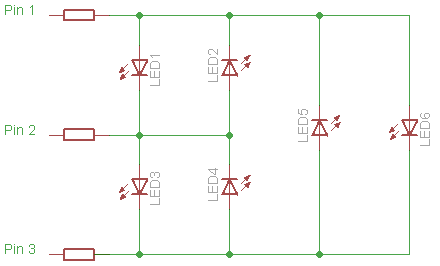
So, the problem is that with an ATtiny, if you don't want to mess with the reset pin, you only have 5 I/O pins available. I want to use two pins as input - a potentiometer and a push button. This would leave me 3 pins for controllign LEDs... not much to play with really. That's where charlieplexing comes in. I can control 6 LEDs using these 3 uC pins.

The wikipedia article on charlieplexing is pretty good, so I won't repeat what's already been said. Take a look at the tri-state logic part to see what's going on here. There are a load of Instructables which cover charlieplexing - this one on the theory is worth a read.

In the code below the LEDs are numbered slightly differently than exactly the same as in the wikipedia diagram (I just soldered up a prototype and the wiring is much easier to route with the wikipedia numbering). The trick is that we switch two pins to output and one as a high-impedance input (this is the 'floating' pin that is effectively taken out of consideration). One input is set high (+Vcc) and one is low (0v). Current is sourced by the +Vcc output pin and sunk by the 0v output pin. So, for each LED we have different data direction (DDRxn) and port (PORTxn) register settings.

In order to control the 6 LEDs in the diagram above we use the following settings:

LEDPIN1PIN2PIN3
1+Vcc0vInput
20v+VccInput
3Input+Vcc0v
4Input0v+Vcc
50vInput+Vcc
6+VccInput0v

The code below is just an initial test set-up where we activate LEDs in a scanning pattern (classic 'cylon eye'). It has all the basics necessary to implement the more complex behaviours. Having the structure array hold the PORTB and DDRB values makes controlling individual LEDs very easy. I'm hoping this will scale up to allowing PWM, but I haven't put much thought into that yet.

Hopefully I'll get a chance to make the UV LED gizmo this week and post about the results.

You can download the source-code from github or use the cut and paste options in the top right of the code box below.

/*
* charlieplex_test.c
*
* Running on an ATtiny45.
*
* Here we control 6 LEDs through 3 pins (PB0:2).
*
* In order to illuminate each LED we do the following:
*
* LED1 - PB0 & 2 output PB2 input. PB0 sourcing, PB1 sinking. Pull-up on PB2
* LED2 - PB0 & 2 output PB2 input. PB1 sourcing, PB0 sinking. Pull-up on PB2
* LED3 - PB1 & 3 output PB0 input. PB1 sourcing, PB2 sinking. Pull-up on PB0
* LED4 - PB1 & 3 output PB0 input. PB2 sourcing, PB1 sinking. Pull-up on PB0
* LED5 - PB0 & 3 output PB1 input. PB0 sourcing, PB2 sinking. Pull-up on PB1
* LED6 - PB0 & 3 output PB1 input. PB2 sourcing, PB0 sinking. Pull-up on PB2
*
* This little ASCII diagram shows the wiring and orientation of the 6 LEDs.
* The hyphens ('-') identify the cathode pins of the LEDs.
*
* PB0 ----------------------
*        |   -      |      |
*        1   2      |      |
*        -   |      |      -
* PB1 --------      5      6
*        |   -      -      |
*        3   4      |      |
*        -   |      |      |
* PB2 ----------------------
*
* Only a single LED can be illuminated at any point in time.
*
* Distributed under Creative Commons 3.0 -- Attib & Share Alike
*
*  Created on: Feb 27, 2010
*      Author: PaulBo
*/
#include <avr/io.h>
#include <util/delay.h>

#ifndef F_CPU
#define F_CPU 1000000UL
#endif

#define DELAY_TIME 50
#define N_LED 6

// see class comments for pin setting explanation
// unused pins are set to input with pull-up resistors activated
struct leds {
uint8_t mDdrB;
uint8_t mPortB;
} ledData[] = {
{0b00011011, 0b11100101},
{0b00011011, 0b11100110},
{0b00011110, 0b11100011},
{0b00011110, 0b11100101},
{0b00011101, 0b11100011},
{0b00011101, 0b11100110}
};

int main()
{
uint8_t i;
for(;;)
{
for(i = 0; i < N_LED - 1; i++)
{
DDRB = ledData[i].mDdrB;
PORTB = ledData[i].mPortB;
_delay_ms(DELAY_TIME);
}
for(i = N_LED - 1;i > 0; i--)
{
DDRB = ledData[i].mDdrB;
PORTB = ledData[i].mPortB;
_delay_ms(DELAY_TIME);
}
}
}

Sunday, February 7, 2010

RGB Night-lights


My kids love lights; flashlights, LEDs, house lights, pen-lights, light-up teddy bears, the northern lights... you name it, they love it. I've been playing around with RGB LEDs for another project along with ping-pong ball diffusers and baby jar containers. It occurred to me that I could make a simple night-light with most of the same components & the girls were bound love 'em.

I put it all together on Saturday evening after the girls were in bed. I think I'm getting better at all this as I had the code working and 2 lights put together by midnight. The girls found them in the morning (unfortunately, very early...) and came into our bedroom to play with them. First off, they played some kind of colour matching game where they were shouting (yes, shouting, early, in bed...) "RED! I'm wearing red!", "Blue! My socks are blue!". After a bit of this they moved into their bedroom to make a 'tent' out of a couple of chairs and a duvet (comforter). They played with the lights in there for a while; I'm not sure what they were doing as I was drifting in and out of consciousness.

It's Sunday and I've just put the kids to bed. They wanted to go to bed with their lights right next to them. I declare them a success!


I apologise for the quality of this video. It was taken on an iPhone and I've not been able to get hold of them again to take a proper vid. I'm sure you get the idea though.


Ingredients:


  • ATtiny13
  • RGB LED (common anode)
  • 8 pin DIP socket
  • switch (the ones I used were SPDT)
  • coin cell battery holder
  • coin cell battery
  • baby jar
  • hookup wire (I used stranded 24 AWG).
  • ping pong ball
  • neodymium magnet
I used the magnet to attach everything to the lid of the baby jar. I've not had much luck with hot-glue and lids (metal ones), so I figured this should work better. I decided to put this together free-form (i.e. no perfboard), mainly for space reasons - but also as I like the aesthetics of the free-form projects (like this advent wreath or this programmable led).

First off I realised that the DIP socket would fit nicely onto the side of my coin cell holders:


Then I added the neodymium magnet to the center of the holder:


This was actually a bad idea... these things are very strong and everything you're playing with at this point has some kind of ferrous metal involved. This thing attracted the soldering iron, the solder, cut off leads, pliers, the helping hand... If I do this again, I'd definitely wait until the end to attach the magnets.

Next step was to solder on the RGB LED:


You may notice that the socket has changed orientation. I was planning on attaching wire to the leads of the LED so that it'd be easily positionable. Then I realised that, since I only had a tiny amount of room in the jar, I could leave the LEDs leads in place and bend them to put the LED into the correct position. That meant re-orientating the DIP socket (as seen above).

The LEDs common anode has not been attached at this point. I added some heat-shrink tubing to this lead to insulate it from the others. It has to be bent forward and could easily touch one of the adjacent leads.

Also, I sanded the LED casing to diffuse the light. Without this step there are obvious areas of red/green/blue that shine on the ping pong ball from the LED.

Now all that's left is the final bit of wiring:


I attached the switch to Vcc and added a ground wire from the battery holder to the DIP socket. The wire is bent around the magnet and was, er... "fun" to solder in place. The soldering iron kept 'pinging' onto the magnet just as I was getting into position... like I said before, put the magnet on last!

I decided to house the lights in baby food jars. The only modification was to cut some holes for my switches (I used a Proxxon rotary tool for this).

Here's a few shots of them in working order:


Code:

I'm running the ATtiny at 8MHz. This requires setting the fuse bits because the default setting is to divide the clock by 8. This code uses the same software PWM as the firefly-jar-II I wrote about previously. No other tricks here, other than a hack (in the main method) to increase the duration of the RedToYellow transition. That's just personal taste though & (since I'm fickle) I may remove that section in the future.

Current code is available on github. Here's the code that's running in my kids bedroom at the time of posting:

/*
 * rgb_strobe.c
 *
 * Distributed under Creative Commons 3.0 -- Attib & Share Alike
 *
 *  Created on: Feb 6, 2010
 *      Author: PaulBo
 */
#include <avr/io.h>
#include <avr/interrupt.h>
#include <util/delay.h>

#ifndef F_CPU
    #define F_CPU 8000000UL
#endif

//Hardware definitions
#define RED_LED      PB2
#define GREEN_LED    PB1
#define BLUE_LED     PB0
#define ALL_LEDS    ((1 << RED_LED) | (1 << GREEN_LED) | (1 << BLUE_LED))

//Maximum value for led brightness
#define R_MAX 255
#define G_MAX 255
#define B_MAX 255

#define RED_INDEX   0
#define GREEN_INDEX 1
#define BLUE_INDEX  2

//Cycle States
#define RedToYellow     0
#define YellowToGreen   1
#define GreenToCyan     2
#define CyanToBlue      3
#define BlueToMagenta    4
#define MagentaToRed     5

//set red to max (we start in the RedToYellow state)
volatile unsigned char mRgbBuffer[] = {0,0,0};
unsigned char mRgbValues[] = {255,0,0};
unsigned char mState;

void init_timers()
{
    TIMSK0 = (1 << TOIE0);         // enable overflow interrupt
    TCCR0B = (1 << CS00);          // start timer, no prescale

    //enable interrupts
    sei();
}

void rgbCycle(){
    switch (mState) {
    case RedToYellow:
        mRgbValues[GREEN_INDEX]++;
        if (mRgbValues[GREEN_INDEX] == G_MAX)
            mState++;
        break;
    case YellowToGreen:
        mRgbValues[RED_INDEX]--;
        if (mRgbValues[RED_INDEX] == 0)
            mState++;
        break;
    case GreenToCyan:
        mRgbValues[BLUE_INDEX]++;
        if (mRgbValues[BLUE_INDEX] == B_MAX)
            mState++;
        break;
    case CyanToBlue:
        mRgbValues[GREEN_INDEX]--;
        if (mRgbValues[GREEN_INDEX] == 0)
            mState++;
        break;
    case BlueToMagenta:
        mRgbValues[RED_INDEX]++;
        if (mRgbValues[RED_INDEX] == R_MAX)
            mState++;
        break;
    case MagentaToRed:
        mRgbValues[BLUE_INDEX]--;
        if (mRgbValues[BLUE_INDEX] == 0)
            mState++;
        break;
    }

    //state should never advance beyond 5.
    //It wraps back to 0 when we reach 6
    mState %= 6;
}

int main(void){
    //Set LED pins to output
    DDRB |= ALL_LEDS;

    init_timers();

    while (1) {
        rgbCycle();
        _delay_ms(250);

        //I like the orange state and it only lasts for a second
        //so lets extend it a little bit more
        if(mState == RedToYellow)
        {
            _delay_ms(250);
            _delay_ms(250);
        }
    }
    return 0;
}

/*
 * Timer/Counter overflow interrupt. This is called each time
 * the counter overflows (255 counts/cycles).
 */
ISR(TIM0_OVF_vect)
{
    //static variables maintain state from one call to the next
    static unsigned char sPortBmask = ALL_LEDS;
    static unsigned char sCounter = 255;

    //set port pins straight away (no waiting for processing)
    PORTB = sPortBmask;

    //this counter will overflow back to 0 after reaching 255.
    //So we end up adjusting the LED states for every 256 interrupts/overflows.
    if(++sCounter == 0)
    {
        mRgbBuffer[RED_INDEX] = mRgbValues[RED_INDEX];
        mRgbBuffer[GREEN_INDEX] = mRgbValues[GREEN_INDEX];
        mRgbBuffer[BLUE_INDEX] = mRgbValues[BLUE_INDEX];

        //set all pins to low (remember this is a common anode LED)
        sPortBmask &=~ ALL_LEDS;
    }
    //this loop is considered for every overflow interrupt.
    //this is the software PWM.
    if(mRgbBuffer[RED_INDEX]   == sCounter) sPortBmask |= (1 << RED_LED);
    if(mRgbBuffer[GREEN_INDEX] == sCounter) sPortBmask |= (1 << GREEN_LED);
    if(mRgbBuffer[BLUE_INDEX]  == sCounter) sPortBmask |= (1 << BLUE_LED);
}