I've heard a lot about charlieplexing since starting out on the electronics adventure & the idea of controlling lots of LEDs from only a few microcontroller pins is very appealing. I've been wanting to make some interesting ways to play with the glow-in-the-dark wall and this has lead me to my first practical use for charlieplexing. I thought that a controllable row of LEDs would open up a lot of possibilities: scan back and forth for a sine wave; all LEDs on for caligraphy; random flash for making star-scapes; POV style message writing; printing patterns - hearts, smileys etc.
So, the problem is that with an ATtiny, if you don't want to mess with the reset pin, you only have 5 I/O pins available. I want to use two pins as input - a potentiometer and a push button. This would leave me 3 pins for controllign LEDs... not much to play with really. That's where charlieplexing comes in. I can control 6 LEDs using these 3 uC pins.
The wikipedia article on charlieplexing is pretty good, so I won't repeat what's already been said. Take a look at the tri-state logic part to see what's going on here. There are a load of Instructables which cover charlieplexing - this one on the theory is worth a read.
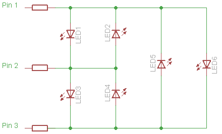
In the code below the LEDs are numbered
In order to control the 6 LEDs in the diagram above we use the following settings:
| LED | PIN1 | PIN2 | PIN3 |
| 1 | +Vcc | 0v | Input |
| 2 | 0v | +Vcc | Input |
| 3 | Input | +Vcc | 0v |
| 4 | Input | 0v | +Vcc |
| 5 | 0v | Input | +Vcc |
| 6 | +Vcc | Input | 0v |
The code below is just an initial test set-up where we activate LEDs in a scanning pattern (classic 'cylon eye'). It has all the basics necessary to implement the more complex behaviours. Having the structure array hold the PORTB and DDRB values makes controlling individual LEDs very easy. I'm hoping this will scale up to allowing PWM, but I haven't put much thought into that yet.
Hopefully I'll get a chance to make the UV LED gizmo this week and post about the results.
You can download the source-code from github or use the cut and paste options in the top right of the code box below.
/*
* charlieplex_test.c
*
* Running on an ATtiny45.
*
* Here we control 6 LEDs through 3 pins (PB0:2).
*
* In order to illuminate each LED we do the following:
*
* LED1 - PB0 & 2 output PB2 input. PB0 sourcing, PB1 sinking. Pull-up on PB2
* LED2 - PB0 & 2 output PB2 input. PB1 sourcing, PB0 sinking. Pull-up on PB2
* LED3 - PB1 & 3 output PB0 input. PB1 sourcing, PB2 sinking. Pull-up on PB0
* LED4 - PB1 & 3 output PB0 input. PB2 sourcing, PB1 sinking. Pull-up on PB0
* LED5 - PB0 & 3 output PB1 input. PB0 sourcing, PB2 sinking. Pull-up on PB1
* LED6 - PB0 & 3 output PB1 input. PB2 sourcing, PB0 sinking. Pull-up on PB2
*
* This little ASCII diagram shows the wiring and orientation of the 6 LEDs.
* The hyphens ('-') identify the cathode pins of the LEDs.
*
* PB0 ----------------------
*        |   -      |      |
*        1   2      |      |
*        -   |      |      -
* PB1 --------      5      6
*        |   -      -      |
*        3   4      |      |
*        -   |      |      |
* PB2 ----------------------
*
* Only a single LED can be illuminated at any point in time.
*
* Distributed under Creative Commons 3.0 -- Attib & Share Alike
*
*  Created on: Feb 27, 2010
*      Author: PaulBo
*/
#include <avr/io.h>
#include <util/delay.h>

#ifndef F_CPU
#define F_CPU 1000000UL
#endif

#define DELAY_TIME 50
#define N_LED 6

// see class comments for pin setting explanation
// unused pins are set to input with pull-up resistors activated
struct leds {
uint8_t mDdrB;
uint8_t mPortB;
} ledData[] = {
{0b00011011, 0b11100101},
{0b00011011, 0b11100110},
{0b00011110, 0b11100011},
{0b00011110, 0b11100101},
{0b00011101, 0b11100011},
{0b00011101, 0b11100110}
};

int main()
{
uint8_t i;
for(;;)
{
for(i = 0; i < N_LED - 1; i++)
{
DDRB = ledData[i].mDdrB;
PORTB = ledData[i].mPortB;
_delay_ms(DELAY_TIME);
}
for(i = N_LED - 1;i > 0; i--)
{
DDRB = ledData[i].mDdrB;
PORTB = ledData[i].mPortB;
_delay_ms(DELAY_TIME);
}
}
}


2 comments:
I've never tried this, but it's a neat idea and I like the name.
One alternative is to use the a shift register. On the plus side, you can have more than one LED On at once, on the minus it may be slower to clock the data in there.
http://www.allaboutcircuits.com/vol_4/chpt_12/4.html
Charlie.
Thanks for the tip. I've not used shift registers. That's something else for me to try out :)
Post a Comment